Do-It-Yourself: Difference between revisions
Jump to navigation
Jump to search
No edit summary |
|||
| Line 36: | Line 36: | ||
= Electricity = | = Electricity = | ||
== Safety == | |||
* Be careful to always check (with a voltage tester) if there is live current on a wire before performing an operation on it (or near it). Even if it's after a switch or something that seems to act as a switch. There is a high risk of electrocution if you don't do that, be really careful about testing, and don't think that "there is no live current there so it should be OK". | |||
== Toggle Switches == | == Toggle Switches == | ||
* For a 3 position toggle switch, normally only 3 pins are required (one input to carry the phase, and two outputs to carry the phase to the motor various inputs). I bought a 4 pin one, you can just ignore / not use the second input pin and it works correctly. Note that the neutral and protective earth wires should be connected separately from the switch. | * For a 3 position toggle switch, normally only 3 pins are required (one input to carry the phase, and two outputs to carry the phase to the motor various inputs). I bought a 4 pin one, you can just ignore / not use the second input pin and it works correctly. Note that the neutral and protective earth wires should be connected separately from the switch. | ||
* I also bought a double (twin) toggle switch which just contains two independent toggle switches. For AC current, the live wire should be duplicated (easy with a three port electrical connector) to both entry pins. Then the two load wires should be connected to the device(s) and to the load pins of the switch. The neutral wire should be connected directly to the motor / device, bypassing the switch. In my case, there were 3 pins per circuit (so a total of 6 pins), so one pin in each circuit was not used (it would probably be used only for DC current). It was important to connect the live wire and load wire to the correct pins, else the switch would not work. On the following picture, the live wire was connected to the left silver pin (marked as +) and the load wire (from the device) to the middle silver pin. The golden pin was not used at all. | |||
[[File:Twin-Switch.webp|center|thumb]] | |||
== Capacitors == | == Capacitors == | ||
Revision as of 09:37, 14 October 2024
General
- At height, always work with a stepladder (as high as possible). Do not use a chair to drill, screw, etc. at height.
- When you're about to disassemble something, make sure you take as many pictures as possible of the mechanism (all sides, aspects, etc). This will be very useful when assembling the system back, as you will forget how it was initially while repairing or fixing.
Fasteners
Screws
- Screws are the most common type of fastening mechanism. They come in many different varieties.
Rivets
- Rivets are an alternative to screws. However, they have the disadvantage that they are permanent; if you need to untie what you fastened, you will destroy the rivet while removing it.
- You can differentiate between a screw and a rivet if you don't see any imprint in the head. Usually the rivet will just have a hole (circle) in the middle of the head.
- There are various types of rivets, for instance:
- Blind rivets;
- Tubular rivets.
- To remove a rivet, you will need a drill (with a metal drill bit). See this tutorial. If the rivet head does not come off, drill deeper: you may have to drill quite a bit before it gets off and can be removed.
Dowels
- The type of material is extremely important. For plaster you have to take general material dowels.
- There are also nylon dowels.
Electric connectors
- Spade connectors, that can be used to wire electric circuits, must be crimped with a proper tool (don't use tape). Crimp at the middle section of the spade connector.

- Electric dominos are being replaced by electric connectors that don't require screwing.
-
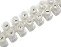 Electric domino
 -
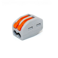 Electric connector


Electricity
Safety
- Be careful to always check (with a voltage tester) if there is live current on a wire before performing an operation on it (or near it). Even if it's after a switch or something that seems to act as a switch. There is a high risk of electrocution if you don't do that, be really careful about testing, and don't think that "there is no live current there so it should be OK".
Toggle Switches
- For a 3 position toggle switch, normally only 3 pins are required (one input to carry the phase, and two outputs to carry the phase to the motor various inputs). I bought a 4 pin one, you can just ignore / not use the second input pin and it works correctly. Note that the neutral and protective earth wires should be connected separately from the switch.
- I also bought a double (twin) toggle switch which just contains two independent toggle switches. For AC current, the live wire should be duplicated (easy with a three port electrical connector) to both entry pins. Then the two load wires should be connected to the device(s) and to the load pins of the switch. The neutral wire should be connected directly to the motor / device, bypassing the switch. In my case, there were 3 pins per circuit (so a total of 6 pins), so one pin in each circuit was not used (it would probably be used only for DC current). It was important to connect the live wire and load wire to the correct pins, else the switch would not work. On the following picture, the live wire was connected to the left silver pin (marked as +) and the load wire (from the device) to the middle silver pin. The golden pin was not used at all.

Capacitors
- If you don't have a multimeter with built-in capacity measurement, you can check if a capacitor is working with the classic resistance mode. Check this link, second method.
- To ensure a proper measure, make sure you discharge the capacitor fully first (by connecting the two electrodes). Also you may need to choose a high limit (2M Ohms was needed in my case). If the measure goes quickly over the limit, the capacitor is not working correctly: numbers should take several seconds and increase steadily if the capacitor is functional.
Electrical adapters
- What is important is that the voltage between the adapter and the device matches. Then the power of the transformer can be higher, it is not a problem (this corresponds to a higher amperage). If the power is lower (lower amperage) the device is not at risk, it is the transformer that will heat up and wear out (it will often blow quickly).
- Note: the power corresponds to the product of the voltage and the intensity. Example: 12v x 3A = 36 Watts.
Sockets and Plugs
- For laptop power adapters, connectors can be of the C5 type, while connectors to desktop PCs are usually C13. These are the female connectors, the corresponding male ones are C6 / C14. See this page for details.
- Switzerland T12 / C5 cables are available.
Lighting
- Bulb power:
- 40 W -> very low.
- 70 W -> low.
- 500 W -> very good.
- Technology:
- LED: best type available currently (2024). Low consumption.
- Halogen: best power, high consumption, heat.
- Compact fluorescent: good consumption, OK power, unfortunately there is a lighting time for high power. Obsolete.
- Incandescent: worst consumption. Obsolete.
Shutters
- For Somfy motors (and probably others), when checking if the motor works correctly (after changing a capacitor for instance), make sure it is fully installed in the axis AND the panel is attached to it. Don't test outside the axis, or without the panel. It seems there are several security or detection mechanisms to prevent the wheel from turning in some cases (while no weight is detected, probably). In particular, it's totally normal that the wheel at the end of the motor only turns manually in one direction when the motor is considered independently. It will work correctly once fully assembled and attached to the panel.
- While fixing a Somfy motor, if possible don't touch the starred wheel at the end of one side of the motor. The screwing mechanism seems complex, and once I destroyed it inadvertently. I screwed it back with only the screw, which seems to work, but it's not the correct original mechanism.
- Adjusting the end stops on a Somfy shutter is important, but depends on the particular model. It usually involves manipulations with particular command sequences. Refer to the manual corresponding exactly to the Somfy model.
Plumbing
- Angle valves (such as this one) can be controlled with the screw under the end cap.
- TPFL joints should always be done in the screwing direction. This video is very useful to understand the logic; if it's not done in the correct direction, the TPFL headband can be removed.